
- Product Catagory
- Tensile Strength Testing Machine
- Cables Flammability Testing Equipment
- Building Materials Flammability Testing Equipment
- Luggage Test Machine
- Textile Testing Equipment
- Color Fastness Instruments
- Textile Physical Test Instruments
- Lab Dyeing Instruments
- Flammability Test Chamber for Textile
- Consumables for Textile Testing
- Toys Safety Testing Equipment
- Physical & Mechanical Testing
- Flammability Testing
- Clamps for Toy Testing
- EN71-8,ISO8124-4
- Furniture Testing Machine
- Chair Testing Machine
- Mattress Testing Machine
- Furniture Testing Equipment
- Tables Test Machines
- Enviromental Chamber
- Leather and Footwear Testing Instruments
- Mobile Phone Testing Equipment
- Contact us
- Tel:86-769-23830463,86-13751491529
- Fax:86-769-38818154
- Contact:Ivy Xie
 [email protected]
 - Msn
 [email protected]
- Whatsapp/Wechat +8613751491529
- Skype
 skylineinstruments
- happy_go_lucky4477
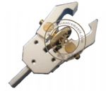
- Site:Home > Toys Safety Testing Equipment > EN71-8,ISO8124-4 > Impact Head from Swing Elements (without Accelerometer)
- Product Images
- detailed description
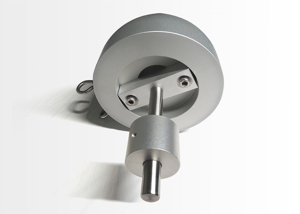
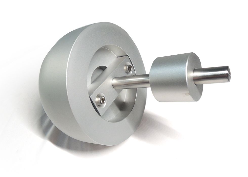
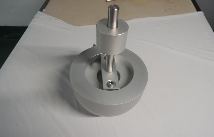
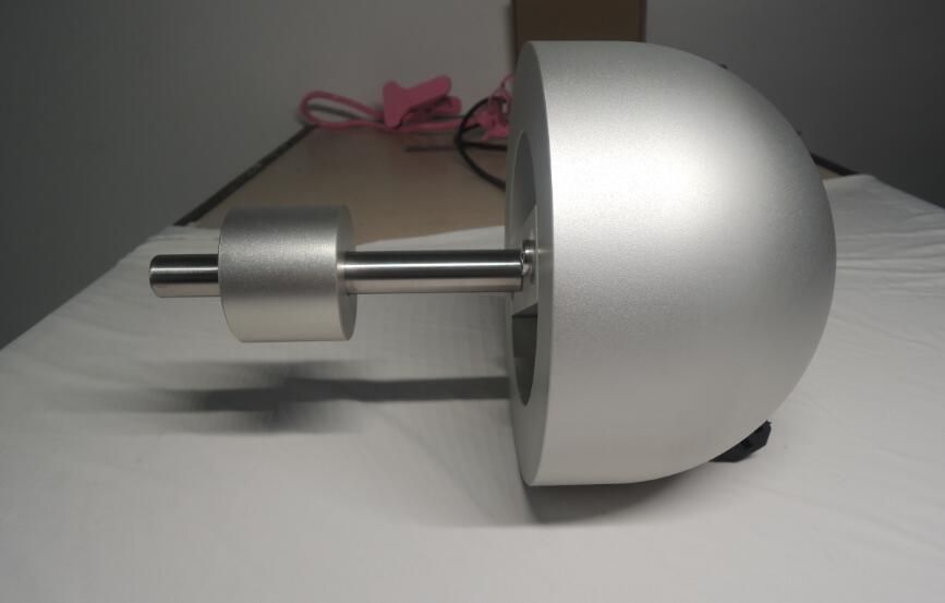
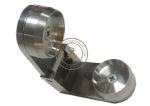
ISO 8124-4 Impact Head from swing elements (without Accelerometer)
Product introduction
Test mass, consisting of an aluminium sphere or semi-sphere of radius 80 mm ± 3 mm, and a total mass (including accelerometer) of 4,6 kg ± 0,05 kg. The impacting part between the surface struck and the accelerometer shall be homogeneous and free from voids. Cables connected to the accelerometer shall be placed in such a way that the effect on the mass of the test mass is minimized
Test Standard
ISO8124-4 6.4.1Procedure
Assemble and install the swing element to be tested in accordance with the manufacturer's instructions.
Suspend the swing with the means of suspension that has been supplied with the swing and at the maximum height that these permit. If ropes or cables are the means of suspension, they may need to be stretched in order to allow smooth travel when the swing is released during the test. If needed, apply a load of, for example, 5 kg to the end of each rope or cable and leave it for 6 h or until the ropes or cables have been straightened.
Adjust all parts of the set-up so that the suspending chains for the test mass are parallel to the means of suspension for the swing element.
Suspend and adjust the test mass so that the contact point of the swing element and the centre of the test mass are in the same horizontal plane as the centre of gravity of the test mass. Ensure that the chains for test mass are not twisted and that the test mass hangs in a vertical line.
Affix an index mark to the side of swing elements that are supported by chains, ropes, cables or other non-rigid suspending elements. The index mark may be on any part of the suspended member that is immediately below the pivot point in the free-hanging rest position.
Swing elements that are supported by chains, ropes, cables or other non-rigid suspending elements shall be raised along their arc of travel until the side-view projection of a straight line through the pivot point and index mark forms an angle of 60° ± 1° with the vertical. Once the suspended member is raised to the test position, some curvature will be produced in the suspending elements. Adjust the suspended member position to determine that curvature which provides a stable trajectory.
NOTE: This item is in stock.

- Related ProductsMore>>